555 Timer Schematic Diagram / 555 Precision Timer Tester Circuit - The control input is used in some of the applications, but most of the applications the control input is not used hence the control voltage is equal to +2/3 vcc.
byAdmin-
0
555 Timer Schematic Diagram / 555 Precision Timer Tester Circuit - The control input is used in some of the applications, but most of the applications the control input is not used hence the control voltage is equal to +2/3 vcc.. (output) circuit diagram of traffic light control mini project 555 timer helpers schematic the addition of a capacitor to the trigger will not work for short output pulses as there is also a short delay in the recovery of the trigger terminal voltage. Apr 15, 2020 · people know it as the 555 timer ic. Then the bistable 555 timer is stable in both states, "high" and "low". The control input is used in some of the applications, but most of the applications the control input is not used hence the control voltage is equal to +2/3 vcc.
The below figure is the schematic of a simple automatic on off timer with a fixed timing resistor and capacitor. We can use the 555 as a timer for up to 10 minutes. You can explore various applications based on monostable multivibrator in 555 timer circuits. This 555 timer circuit will remain in either state indefinitely and is therefore bistable. Apr 15, 2020 · people know it as the 555 timer ic.
Led Dimmer Circuit With 555 Timer Hackster Io from hackster.imgix.net (output) circuit diagram of traffic light control mini project 555 timer ic (as a pulse generator) 4017 ic counter (main ic of the circuit) 1m potentiometer (controls the timing of pulse generated by 555 timer) red, yellow and green leds. Simple ne555 ic tester circuit diagram The threshold input (pin 6) is connected to ground to ensure that it cannot reset the bistable circuit as it would in a normal timing application. Jul 24, 2019 · the working principle of the 555 timer is by considering the block diagram of the 555 timer ic. Sep 29, 2015 · you can also calculate the t with this 555 timer monostable calculator. This 555 timer circuit will remain in either state indefinitely and is therefore bistable. You can explore various applications based on monostable multivibrator in 555 timer circuits.
Learn by doing is the best.
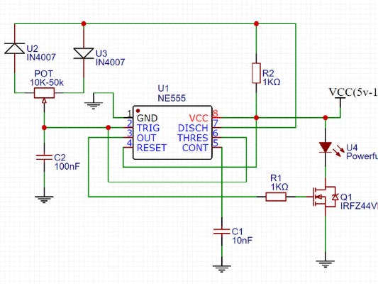
Above schematic diagram shows the 555 timer monostable multivibrator circuit. This circuit is also called a delay. Apr 15, 2020 · people know it as the 555 timer ic. We can use the 555 as a timer for up to 10 minutes. Learn by doing is the best. The first comparator has threshold input to pin 6 and control inputs for pin 5. Simple ne555 ic tester circuit diagram The below figure is the schematic of a simple automatic on off timer with a fixed timing resistor and capacitor. The second 555 timer helper will extend the timers output duration without having to use large values of r1 and/or c1. Jul 24, 2019 · the working principle of the 555 timer is by considering the block diagram of the 555 timer ic. The control input is used in some of the applications, but most of the applications the control input is not used hence the control voltage is equal to +2/3 vcc. 555 timer helpers schematic the addition of a capacitor to the trigger will not work for short output pulses as there is also a short delay in the recovery of the trigger terminal voltage. Then the bistable 555 timer is stable in both states, "high" and "low".
You can explore various applications based on monostable multivibrator in 555 timer circuits. 555 timer ic (as a pulse generator) 4017 ic counter (main ic of the circuit) 1m potentiometer (controls the timing of pulse generated by 555 timer) red, yellow and green leds. This circuit is also called a delay. We can use the 555 as a timer for up to 10 minutes. 555 timer helpers schematic the addition of a capacitor to the trigger will not work for short output pulses as there is also a short delay in the recovery of the trigger terminal voltage.
Circuit Diagram 555 Timer Monostable Wiring Library from 4.bp.blogspot.com (output) circuit diagram of traffic light control mini project We can use the 555 as a timer for up to 10 minutes. Above schematic diagram shows the 555 timer monostable multivibrator circuit. The first comparator has threshold input to pin 6 and control inputs for pin 5. The second 555 timer helper will extend the timers output duration without having to use large values of r1 and/or c1. So the time period after which this circuit will automatically turn on/off the output is fixed and can be found out by using the formula mentioned in the calculation section. Apr 15, 2020 · people know it as the 555 timer ic. Then the bistable 555 timer is stable in both states, "high" and "low".
So the time period after which this circuit will automatically turn on/off the output is fixed and can be found out by using the formula mentioned in the calculation section.
(output) circuit diagram of traffic light control mini project This 555 timer circuit will remain in either state indefinitely and is therefore bistable. You can explore various applications based on monostable multivibrator in 555 timer circuits. So the time period after which this circuit will automatically turn on/off the output is fixed and can be found out by using the formula mentioned in the calculation section. Apr 15, 2020 · people know it as the 555 timer ic. Simple ne555 ic tester circuit diagram Sep 29, 2015 · you can also calculate the t with this 555 timer monostable calculator. The second 555 timer helper will extend the timers output duration without having to use large values of r1 and/or c1. 555 timer helpers schematic the addition of a capacitor to the trigger will not work for short output pulses as there is also a short delay in the recovery of the trigger terminal voltage. Learn by doing is the best. Above schematic diagram shows the 555 timer monostable multivibrator circuit. Jul 24, 2019 · the working principle of the 555 timer is by considering the block diagram of the 555 timer ic. The threshold input (pin 6) is connected to ground to ensure that it cannot reset the bistable circuit as it would in a normal timing application.
The threshold input (pin 6) is connected to ground to ensure that it cannot reset the bistable circuit as it would in a normal timing application. The below figure is the schematic of a simple automatic on off timer with a fixed timing resistor and capacitor. This circuit is also called a delay. Learn by doing is the best. So the time period after which this circuit will automatically turn on/off the output is fixed and can be found out by using the formula mentioned in the calculation section.
Lc Meter Circuit Using 555 Timer Laptrinhx from www.electronicshub.org The control input is used in some of the applications, but most of the applications the control input is not used hence the control voltage is equal to +2/3 vcc. 555 timer helpers schematic the addition of a capacitor to the trigger will not work for short output pulses as there is also a short delay in the recovery of the trigger terminal voltage. This circuit is also called a delay. (output) circuit diagram of traffic light control mini project 555 timer ic (as a pulse generator) 4017 ic counter (main ic of the circuit) 1m potentiometer (controls the timing of pulse generated by 555 timer) red, yellow and green leds. Apr 15, 2020 · people know it as the 555 timer ic. Simple ne555 ic tester circuit diagram The second 555 timer helper will extend the timers output duration without having to use large values of r1 and/or c1.
Apr 15, 2020 · people know it as the 555 timer ic.
This 555 timer circuit will remain in either state indefinitely and is therefore bistable. 555 timer helpers schematic the addition of a capacitor to the trigger will not work for short output pulses as there is also a short delay in the recovery of the trigger terminal voltage. Then the bistable 555 timer is stable in both states, "high" and "low". So the time period after which this circuit will automatically turn on/off the output is fixed and can be found out by using the formula mentioned in the calculation section. Above schematic diagram shows the 555 timer monostable multivibrator circuit. Learn by doing is the best. Sep 29, 2015 · you can also calculate the t with this 555 timer monostable calculator. The first comparator has threshold input to pin 6 and control inputs for pin 5. (output) circuit diagram of traffic light control mini project We can use the 555 as a timer for up to 10 minutes. You can explore various applications based on monostable multivibrator in 555 timer circuits. 555 timer ic (as a pulse generator) 4017 ic counter (main ic of the circuit) 1m potentiometer (controls the timing of pulse generated by 555 timer) red, yellow and green leds. The below figure is the schematic of a simple automatic on off timer with a fixed timing resistor and capacitor.
The second 555 timer helper will extend the timers output duration without having to use large values of r1 and/or c1 555 timer schematic. Simple ne555 ic tester circuit diagram